Danfoss - Experts & Thought Leaders



































Latest Danfoss news & announcements
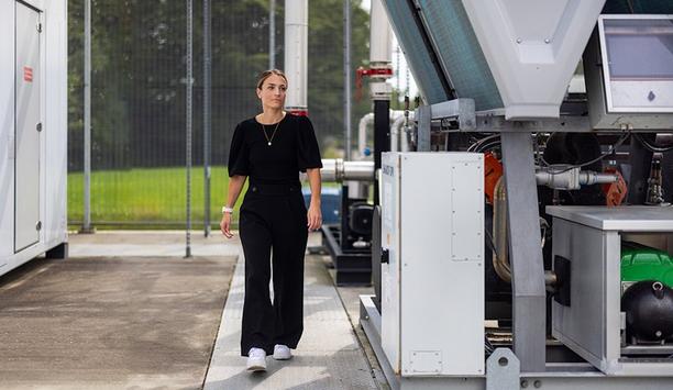
Danfoss has been recognized by CDP for leadership in the categories of Climate Change and Water Security with an A- (A minus) rating. CDP is a global non-profit organization that operates an independent environmental disclosure system. It is recognized as one of the world’s leading environmental benchmarking platforms, rating companies on progress in their environmental performance and their transparency. In 2025, CDP rated nearly 20,000 companies from A to D across more than 130 countries. Achieving an A-rating positions Danfoss among the top performers, demonstrating environmental leadership practices, transparency, and actions that strengthen long-term environmental resilience. Climate change and water security "Sustainability is integral to our purpose of engineering a better future and central to how we create value for our customers. We are proud to be recognized by CDP for the first time in the leadership tier for our actions across climate change and water security." "This great milestone is possible thanks to our dedicated global teams and the strong collaboration we have with our customers and suppliers. It also serves as a benchmark and motivation for continuous improvement in line with our strategy," Kitti Tumbasz, Senior Director, Head of Group Sustainability. Sustainability Leadership The Leadership Rating (A Minus) From CDP Reflects The Momentum Of the Sustainability Journey, Including The Continued Investments In the People, Technology, and Innovation To Deliver Competitive, Innovative, and Sustainable Solutions. As A Technology pioneer, they Have The Solutions To Drive The Green Transition Together With the Customers and Partners. They Will Continue Working To Drive Sustainable Impact And Create Value. Environmental Highlights Selected highlights of Danfoss’ environmental efforts include the continued decoupling of growth from its own CO2 emissions, the ambitious climate targets validated by the science-based targets initiative (SBTi), and the climate transition plan.
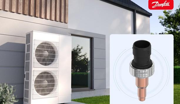
As the latest in the DST series of durable, compact pressure sensors from Danfoss Sensing Solutions, the DST P070 offers a range of features ideally suited for heat pump installations. "Heat pumps play a central role in our transition away from fossil fuel-driven HVAC systems. For example, the REPowerEU targets require that the amount of newly installed heat pumps double every four years, meaning they will need 60 million more heat pumps installed by 2030." "Yet, HVAC system builders often struggle to find sensors compact and lightweight enough to satisfy smaller system requirements. The DST P070 addresses this challenge by offering reliable pressure-sensing technology in a compact design," Iro Dragoumi, Segment manager for HVAC&R at Danfoss Sensing Solutions. Bi-metal pressure connection The pressure sensor features backside MEMS technology which enabled its value, size and weight to be optimal for HVAC applications. The compact bi-metal pressure connection offers the best fit in applications with small and narrow spaces, such as heat pumps, chillers, residential and transport air conditioning units and food service refrigeration. sensor’s lightweight design “The DST P070 offers the shortest solder tube length on the market, a small body sensor and a single-brazing point, all designed to make it easier for installers to work within the space constraints in heat pump installations." "And because of the sensor’s lightweight design, there’s practically no need for vibration support, which makes for a simple, effortless setup,” Katharina Löhden, Product manager for pressure sensors at Danfoss Sensing Solutions. Simplifying the installation process In addition to offering the best fit in narrow installation spaces, the bi-metal solder tube also provides several installation benefits. “When you have a pressure sensor with copper solder tubes, you need cooling protection for the sensor during the soldering process. In the DST P070, the pressure connection is made of copper and stainless steel which, in addition to being durable, can eliminate the need for cooling protection during installation. This shortens installation time and makes the entire process easier for the installer.” The bi-metal solder tube also features superior welds to the housing and precision brazing to the pipe. It also has a lower heat transfer than copper or brass, which protects system components and extends the sensor’s lifetime. Fully compatible with low-GWP refrigerants In keeping with the company’s commitment to supporting the HVAC industry through the refrigerant transition, the Danfoss Sensing Solutions team tested the DST P070 across a wide range of refrigerants and oils to ensure its compatibility with A1, A2L, and A3 refrigerants. “We have validated that the DST P070 works with R290, the main heat pump refrigerant, and it’s compatible with the aggressive R1234ze refrigerant as well,” says Iro. The sensor also features the company’s patented sealing technology, ensuring hermetical tightness, and has undergone a series of validation and tightness control tests to confirm it can withstand helium leakage, overpressure, thermal stress and aging, vibration and a combination of temperature and vibration exposure. Test results have been validated by an external laboratory and the DST P070 is ISO 14903 design tested and ATEX Zone 2 & HazLoc compliant. Guaranteeing shorter lead times and supply chain integrity To meet the increasing demand for heat pumps, OEMs need a reliable supplier who can deliver system components on time. “Our customers tell us that they’re looking for global suppliers that can provide high-quality products and round-the-clock support. To accommodate this, we’ve expanded our production footprint and hence created a new, high-volume, fully automated production line in Minden, Germany. This line will enable us to offer our customers shorter lead times, so they receive orders swiftly and efficiently.” The production facility sources 70% of its materials from within the EU and offers full traceability on parts and process data. The site is also ISO 14001, ISO 9001, and IATF 16949 compliant and fully aligned with the company’s ESG commitment. “As is the case with many of our customers, Danfoss is committed to reducing our carbon footprint. In line with these goals, our facility in Minden is on track to be carbon neutral by 2030.” Putting sustainability first: from production to packaging Sustainability has also played a significant role in the entire DST P070 production process, from manufacturing to packaging. “The sensor contains more than 50% recycled stainless steel and it has a lower total carbon footprint, thanks to its compact design and use of fewer materials,” Katharina explains. “We’ve developed a unique pulp tray packaging, which reduces our CO2 emissions by 50% and transport volume. Yet the design offers the same strength and durability to protect sensors during transport.” Combination of a simplified installation process The combination of a simplified installation process, proven quality, low-GWP refrigerant compatibility and ESG-compliance add up to a pressure sensor that equips OEMs to meet market demand, industry regulations and internal sustainability requirements. “In the DST P070, OEMs get a pressure sensor designed to work with heat pumps, chillers and other HVAC applications – one that meets the highest quality standards and that is readily available. And with our end-to-end commitment to sustainable manufacturing, we can offer a component that helps our customers work towards a carbon-neutral future,” concludes Iro.
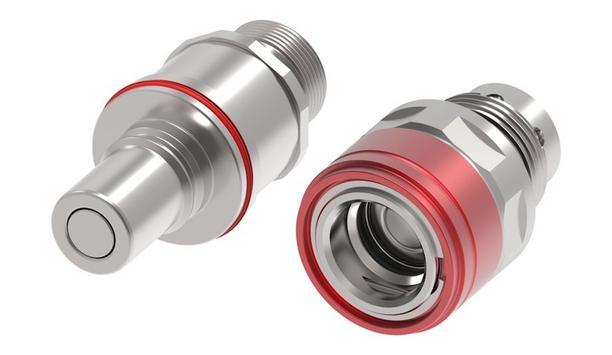
Danfoss Power Solutions announced the launch of its Danfoss Hansen® MQD and MQDB series of quick-disconnect couplings, engineered for single-phase water/glycol cooling systems in electronics and data center liquid cooling applications. The MQD hand-mate and MQDB blind-mate couplings feature a compact design ideal for high-density server racks. The couplings are fully interchangeable with MQD couplings from other vendors. Danfoss MQD and MQDB couplings Danfoss MQD and MQDB couplings maximize reliability while enabling high flow rates and simplified installation and maintenance. Every MQD and MQDB component Danfoss produces is helium-leak tested for maximum integrity. Color-coded connectors offer simple identification. The couplings are available in sizes 02, 03, and 04 (3.3, 4.9, and 6.4-millimeter nominal flow diameters, respectively), with flow rates ranging from 2 to 6.8 liters per minute. Reliability and performance in liquid cooling for AI “Danfoss is proud to have shaped the MQD specification, setting benchmarks for reliability and performance in liquid cooling for AI and high-performance computing. As heat loads increase, liquid cooling is no longer optional — it’s essential,” said Chinmay Kulkarni, Senior Product Manager, Data Center, Danfoss Power Solutions. “Our MQD and MQDB couplings deliver robust performance, safety, and compatibility, making them the ideal choice for next-generation cooling systems for compute trays.” Corrosion resistance plus EPDM seals Danfoss Hansen MQD and MQDB couplings feature 304 stainless steel construction for corrosion resistance plus EPDM seals for durability. The couplings are offered with ISO 11926-3 O-ring boss, BSPP, and hose tail terminal ends for application versatility. The couplings feature an operating temperature range of −40°C to 150°C (−40°F to 302°F).
Insights & Opinions from thought leaders at Danfoss

The data center market has shown robust growth over the past five years, with significant increases in capacity and electricity usage. According to the International Energy Agency (IEA), global data center electricity consumption was approximately 460 TWh in 2022, and it is projected to rise to over 1,000 TWh by 2026. This growth is driven by the increasing demand for digital services and the expansion of artificial intelligence (AI) workloads. In 2025, the total capacity demand for data centers is expected to reach 82 gigawatts (GW), with AI workloads accounting for 44 GW and non-AI workloads for 38 GW. By 2030, this demand is projected to increase to 219 GW, with AI workloads making up 156 GW. This significant growth underscores the importance of sustainable practices in the data center industry. Alternative Off-Grid Power Sources To meet the growing energy demands, data centers are increasingly turning to alternative off-grid power sources. These include solar power, wind turbines, micro-hydro power, and biogas generators. These renewable energy sources not only reduce the carbon footprint of data centers but also enhance their resilience by providing reliable power in remote locations. Green hydrogen, produced by electrolysis using renewable energy, also offers a sustainable alternative to traditional cooling methods, with the potential to significantly reduce greenhouse gas emissions. Continued Compute Growth and Liquid Cooling Nvidia's use of direct-to-chip liquid cooling and closed-loop systems has shown a 300x improvement The rapid growth in compute power, particularly with the introduction of platforms like Nvidia's NVL-576 600 kW, has significant implications for data center cooling. This platform, designed for high-performance AI workloads, requires advanced cooling solutions to manage the heat generated by such dense compute environments. Nvidia's use of direct-to-chip liquid cooling and closed-loop systems has shown a 300x improvement in cooling efficiency. Google's fifth-generation cooling distribution unit (CDU), known as Project Deschutes, is another example of innovation in this space. This CDU sidecar power rack supports up to 1 MW per rack, leveraging high-voltage DC power distribution to enhance efficiency and cooling capacity. Energy-Efficient Cooling Technologies Energy-efficient cooling technologies are critical for the sustainable operation of data centers. Some of the most promising technologies include: Direct-to-Chip Liquid Cooling: This method involves applying liquid coolants directly to the processors, providing superior heat dissipation and enabling servers to operate at optimal performance levels. Hybrid Rear-Door Heat Exchangers: These systems combine air and liquid cooling to manage heat more efficiently, particularly in high-density rack environments. Heat Reuse The elevated temperatures made by liquid cooling can also be harnessed in industrial processes Liquid cooling provides an additional opportunity to reduce energy consumption while enabling data centers to become contributors to community energy systems. Unlike traditional air cooling, which disperses heat into the atmosphere, liquid cooling captures heat more effectively, allowing the heat to be repurposed for the heating needs of nearby residential or commercial buildings. Heat pumps can be employed to raise the temperature of the excess heat to the temperature required by heating systems, resulting in greater energy efficiency. The elevated temperatures produced by liquid cooling can also be harnessed in industrial processes that require specific heat levels, such as pasteurization, drying or chemical processing. By utilizing this heat, industries can reduce their reliance on external energy sources, which in turn lowers operational costs and emissions. However, most areas in the U.S. lack the infrastructure to support district heating. Significant investment is required to develop the infrastructure needed to transport and utilize the heat, such as pipelines for district heating or retrofitting industrial processes. Depending on the region, there may also be legal or regulatory barriers to overcome. Policy and Community Engagement There is strong support for AI growth, with alliances involving companies like OpenAI and Meta Within the current U.S. administration, there is strong support for AI development, with partnerships involving companies like OpenAI and Meta. OpenAI, Meta, SoftBank and Oracle have joined forces for the Stargate Project, which aims to build AI data centers in the U.S. This project includes significant investments to create infrastructure that supports AI development. The Trump administration has identified 16 sites on federal land for the development of AI data centers. These centers are intended to provide the necessary processing capacity for machine learning, cloud storage, and AI systems. Heat reuse offers a powerful tool for sustainability and community engagement. By capturing and repurposing the waste heat, data centers can significantly reduce their environmental impact while providing tangible benefits to surrounding communities and industries. This approach not only supports decarbonization efforts but also fosters stronger ties between data centers and the communities they serve, creating a more sustainable and resilient future. Benefits and integration of data centers Data centers support local economies by creating jobs, providing reliable internet services Educating the community about the benefits of data centers is crucial to ensure the successful integration of data centers into local communities. Data centers support local economies by creating jobs, providing reliable internet services, and enabling technological advancements that improve quality of life. By highlighting these benefits, data centers can build stronger community support and enhance their social license to operate. The effort should combine outreach with online educational initiatives, collaborations with industry, academia, NGOs and multiple sources of in-the-field insight. Conclusion The data center market is poised for continued growth, driven by advancements in technology and increasing demand for digital services. By focusing on sustainability, heat reuse, and energy-efficient cooling technologies, the industry can meet this demand while minimizing its environmental impact. Engaging with communities and educating them about the benefits of data centers will further support the sustainable growth of this vital industry.

As demand continues to grow for sustainable, energy-efficient solutions in refrigeration and heating, both Europe and North America are navigating a rapid transition toward natural refrigerants. There is a strong demand for new CO2 systems, including heat pumps and various other applications. Higher capacity compressors with larger operating envelope, such as Danfoss’ Bock HGX56 CO2 T series, will play a critical role in supporting this growing need. Air to water heat pumps As shown in Figure 1 and Figure 2 below, the larger operating envelope of up to 77°F and 65 bar on the suction side can improve the COP by approximately 15% for applications with higher heat source temperatures – for example, air to water heat pumps in summer conditions. Transcritical CO2 figure. Larger operating envelope of up to 77°F and 65 bar on the suction side. Figure 3 below shows a typical layout of a CO2 transcritical air-to-water heat pump for large systems, designed with features to boost efficiency. Such systems are already being built in Europe, with the largest compressor options, and used in heating capacities of up to 2.5 MW per rack. Layout of a CO2 transcritical air-to-water heat pump for large systems. Cooling and Heating Working Together Transcritical supermarket applications with heat reclaim are very suitable for improving the version Transcritical supermarket applications with heat reclaim are very suitable for improving the overall refrigeration system performance. It is a highly efficient and resilient solution that provides simultaneous heating and cooling by recycling waste heat energy within the store. More than 2,000 installations across Europe and in other parts of the world have shown that the traditional CO2 weaknesses in refrigeration applications, such as high temperatures and pressures, can be turned into profitable advantages when adding heat reclaim to the system. In fact, the operational costs can be reduced by more than 20% by replacing conventional heating sources with heat reclaim, and the pay-back time of the heat reclaim installation is typically short, less than 2.5 years. At the same time, huge carbon savings can be made when the system is installed and maintained correctly. Additional Applications Transitioning to CO2 CO2 is increasing in popularity for cold storage and food processing, due to some challenges of using ammonia in states with a large number of regulations, as well as the desire for distributed systems when expanding plants and the advent of larger CO2 compressors. Some estimates show a 10% market transition to CO2 from ammonia and HFCs for systems up to 250 tons (880 kW). An example would be a cold storage facility requiring variable temperatures with stability/efficiency at partial load for garlic processing, storage and pre-cooling. The requirements for pre-cooling are 40°C/39.20°F, but for processing and final storage, −100°C/140°F is required. CO2 System Examples Single-stage transcritical CO2 applications are used in the field of medium temperature refrigeration Single-stage transcritical CO2 applications are used in the field of medium temperature refrigeration. They can be operated very efficiently, if the high pressure is operated in the subcritical range over a long period. Using the high-pressure side, it is appropriate to use the application in the transcritical range in combination with refrigeration, due to a large temperature glide and a relatively high discharge end temperature for specific heat pumps and the heat recovery. In CO2 applications in low and medium temperature refrigeration, so-called booster systems are used. High-pressure CO2 gas from the low-temperature compressor is discharged directly to the suction side of the second compressor stage. Different plant constructions of these Booster applications are used, for example, in supermarket applications. In a cascade system, different refrigerants are used in an application. They are combined in two refrigerating circuits that are separated from each other. The high temperature stage is used as a condenser in the CO2 application. It is possible to use different refrigerants like hydrocarbons, ammonia, and HFCs like R-134A. Keys to a Successful Installation Proper oil levels, adequate space for maintenance and ventilation, environmental conditions and surface setup with sufficient load-bearing capacity are all critical initial items to consider. Once these items have been considered and addressed properly, then you need to take extreme care during the soldering - cooling the valve body during and after and only using inert gas to inhibit oxidation products. The actual required pipe cross-section must be matched to the output. The tube must be sawed at a right angle with the angular tolerance being ±10. Pipes and system components must be clean and dry inside and free of scale, swarf and layers of rust and phosphate. Only use hermetically sealed parts. Lay pipes correctly. Suitable vibration compensators must be provided to prevent pipes being cracked and broken by severe vibrations. Ensure a proper oil return and keep pressure loss to an absolute minimum. Suction and discharge should be depressurized prior to connecting to the refrigerant system. Proper layout of the suction and pressure lines directly after the compressor is integral to the smooth running and vibration behavior of the system. Oil return function To ensure the oil return function will work reliably no matter what kind of system configuration you are using, Danfoss recommends incorporating oil separators or oil level monitoring equipment. For systems with long pipes and higher degree of contamination, a filter on the suction-side is recommended. When attaching accessories with an electrical cable, a minimum bending radius of 3x the cable diameter must be maintained for laying the cable. Voltage and frequency values Compare the voltage and frequency values with the data for the mains power supply Connect the compressor motor in accordance with the circuit diagram (see inside of terminal box). Compare the voltage and frequency values with the data for the mains power supply. Only connect the motor if these values are the same compressors marked in this way are suitable for direct or part winding start. The motor winding is divided into two parts: part winding 1 = 50 % and part winding 2 = 50 %. This winding division reduces the start-up current during a part winding start to approx. 50 % of the value for a direct start. Reversed fields of rotation In the factory, as shown below in Figure 4, the motor is switched for direct starting (YY). For part winding start (Y/YY), remove the bridges and connect the motor feed cable according to the circuit diagram. The motor is switched for direct starting (YY). Failure to comply results in reversed fields of rotation and can cause motor damage. After the motor has started up with part winding 1, part winding 2 must be switched on after a maximum 1-second delay. Failure to do so can be detrimental to the service life of the motor. Ensure that power is supplied via QA2 to winding 1 (50%) (1U1/1V1/1W1) and via QA3 to winding 2 (50 %) (2U1/2V1/2W1). The motor contactors (QA2/QA3) are each to be rated for approx. 50% of the maximum operating current. Danfoss BOCK compressors Transcritical CO2 compressors, like the Danfoss BOCK product line, offer a wide span of capacities with up to 162 kW of cooling capacity (14°F/95°F/18R/60 Hz) and 420 kW of heating capacity (41°C/77°C (100 bar)/18R/60 Hz) for many different product applications, including food retail, heat pumps, district heating, industrial refrigeration and process heating, reversible chiller/heat pumps for HVAC, cold storage, chillers, and data centers. Low and medium temperature levels are available, with high stand still pressures. This high capacity reduces the need for multiple compressors, simplifying system design and reducing investment costs. The Danfoss BOCK compressors also feature a high-pressure rating of 130 bar in operation/150 bar at stand still on the high side and 65 bar in operation/100 bar at stand still on the low side.

Installing HVAC equipment is not as simple as plugging in an appliance. Installers often face many hurdles, including complex system design, space constraints, accurate sizing and load calculation, and proper ductwork installation. But what are we forgetting? We asked our Expert Panel Roundtable: What is the most overlooked factor when installing HVAC systems?


